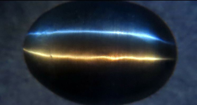
First published in the Spring 2018 issue of Gems&Jewellery, Harold Killingback FGA explores chatoyancy in sillimanite cabochons, an optical phenomenon where a band of light, known as a ‘cat’s eye’, appears to hover above the surface of a stone, resulting in a striking lustre and colour.
Figure 1 shows a sharp cat’s eye in a sillimanite cabochon lit by a single point source (the sun) above the stone, i.e. from the same side from which it is viewed.
There is also a sharp ‘eye’ when the light comes up through the stone, toward the viewer, as shown in Figure 2. One can even see the ‘eye’ when the cabochon, lit from below, is viewed horizontally along the line of the stone’s major axis, see Figure 3.

Figure 1. Epi-chatoyancy, plan view, lit by the sun.
In addition to the ‘eye’ line, there are reflections of the sun and of surroundings from the top surface of the cabochon.
All Image Credits: Harold Killingback FGA.
For these views, the single point of light was a fibre optic ‘pipe’, with an added tube 157 mm long and 10 mm in internal diameter, to fit the pipe. This acts as a collimator – a device that narrows a beam of particles or waves (including light).
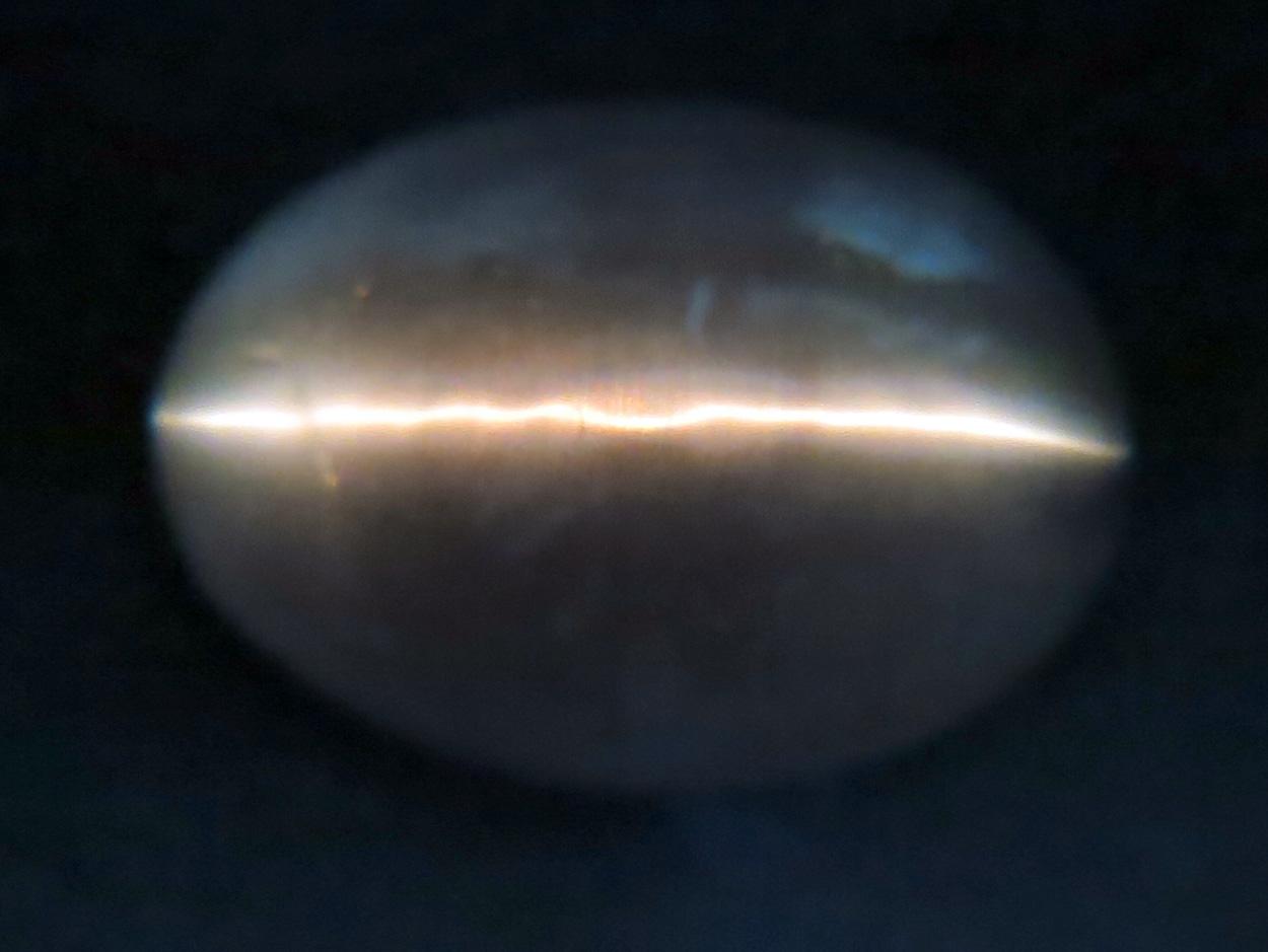
Figure 2. Dia-chatoyancy, plan view.
Light from a fibre optic source below enters the stone through a suitably shaped hole in a black paper mask.
As well as the “eye” line, the fibrous nature of the stone is visible.
It is less usual to see the effects in Figures 2 and 3 (dia-chatoyancy) than that in Figure 1 (epi-chatoyancy), partly because we normally admire gems when lit from above rather than from below, so we may simply miss seeing the effect.
Partly, also, because many chatoyant stones are too opaque to let much light pass right through them. Epichatoyancy, by contrast, can be the result of reflection from parallel inclusions immediately below the surface, and so the light path within the stone can be shorter, resulting in less absorption.
It helps, in this case, that the base of this cabochon is fairly smooth, rather than being left rough ground as is often the case, so more light from below can enter without being scattered.
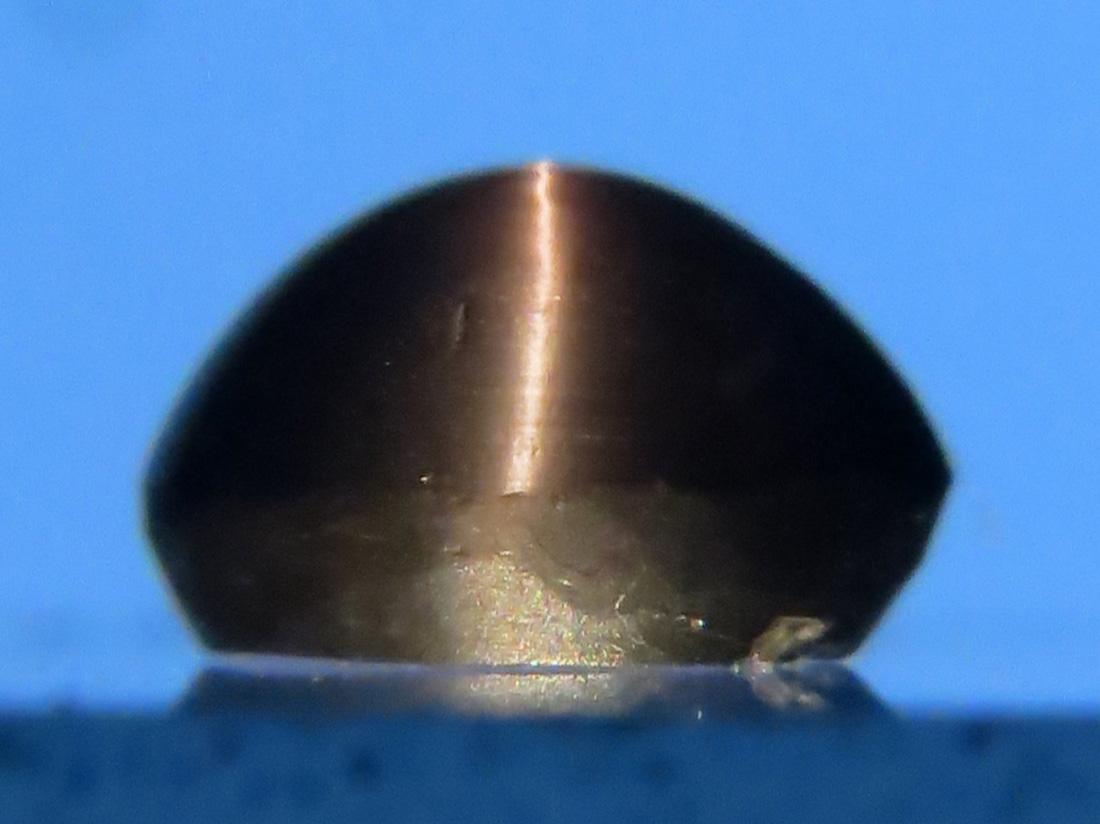
Figure 3. Dia-chatoyancy, end view. The cabochon is resting on a glass slide so that fibre optic light can enter from below.
The background is illuminated by LED light, hence its blueness. Here, also, the fibrous structure of the stone can be seen, orientated at right angles to the bright line.
READ MORE: Insights and Reactions to De Beers’ New Lab-Grown Diamond Jewellery Brand
Sillimanite, with andalusite and kyanite, is a polymorph of aluminium silicate. Its RI is in the range 1.654 -1.683 and DR 0.020 (1). A fibrous form, sometimes called Fibrolite, can exhibit chatoyancy due to its own structure. This example shows such a form.
The chatoyancy of the brown sillimanite from Orissa, India, is said to be due to ultrafine long and short ilmenite needles (2). The stone illustrated might well be from this source as the dealer said it was from India, but he could not be more precise.
I have not, however, been able to see any needles in this example. I put it near a strong magnet, but no attraction was detected. This stone measures 8.5 x 6.1 x 3.7 mm and weighs 1.75 ct.
Ray Diagram
The problem in drawing a ray diagram for chatoyancy is that one does not know where the relevant reflective surface is located within the stone, nor what angle it is orientated.
The solution is to work backwards along the exit ray, and forwards along the incoming ray, and then to see what has to happen where their paths cross if they are to be parts of a single ray.
The resultant diagram is shown in Figure 4, which represents a partial cross-section of the stone along its major axis as viewed from the side. In this example, I have chosen to examine the case of the dia-chatoyancy when the stone is viewed horizontally along the line of its major axis, as in Figure 3.
Arbitrarily, I have selected the horizontal ray leaving the cabochon at the point where the normal to the surface rises at 30º to the horizontal.
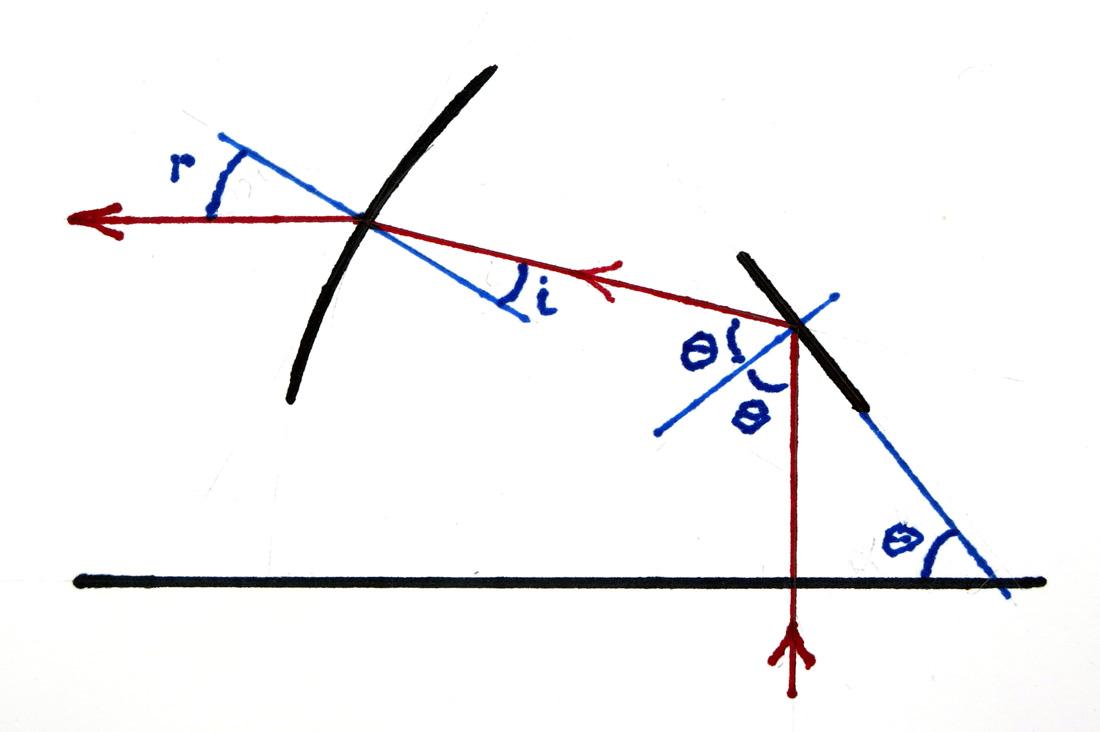
Figure 4. Ray diagram. Arbitrarily, an exit ray has been chosen, and the associated ray before refraction has been calculated.
Another arbitrary choice is shown for the entry ray. The condition that these rays be one continuous ray is met by a reflective surface as shown.
READ MORE: The Geology of Diamonds
As the exit ray is horizontal, the angle of refraction, r, must be 30º. The incident angle, i, was calculated using Snell’s law, and an RI of 1.658. The resultant angle is 17.6º, and so the ray in the stone slopes up from horizontal at an angle of (r – i), which equals 12.4º in the case illustrated.
The arbitrarily chosen entrant ray is not refracted, as it is normal to the base. The angle between it and the exit ray just examined is 90 + (r – i). For these rays to be parts of a single path there must be a reflective surface where they meet. Let it be tilted at θ to the horizontal. As the incident ray at the reflecting surface is vertical, the angle of incidence is also θ, and the angle of reflection must be the same.
So 2θ = 90 + (r – i). In our example we get θ = 51.2º. This angle would be the same had I chosen any other ray in the vertical entrant beam.
We can repeat the calculation of θ corresponding to various exit points of horizontal rays from the stone as defined by the angle of the normal to the surface at these points. The results are shown below.
| Angle of normal at exit point | 15.0 | 30.0 | 45.0 | 60.0 | 75.0 |
| Angle of reflector | 48.0 | 51.2 | 54.9 | 59.2 | 64.7 |
Figure 5 is included for fun, really, but it does illustrate the fact that multiple point sources produce multiple eye-lines. Here, there are but two sources and so two eyes. In the limit, a cloudy sky consists of infinite point sources and produces, not any lines at all, but so many that no individual line can be distinguished and the stone reflects an even glow.

Figure 5. Bi-dia chatoyancy. The white line is produced by a fibre optic incandescent light from below the cabochon.
The blue line is from a LED torch, also from below, but slightly to one side of the other source.
The camera was set to correct for the red cast of tungsten light, so the LED ray looks very blue by comparison. Note the fibrous nature of the stone.
Conclusions
I have calculated the angles of reflector surfaces for only one direction of view and only one of sillimanite’s two values of RI. These reflector angles could all be provided if the reflecting inclusions were roundish in cross-section, whether hollow tubes or fibres.
If, however, the inclusions are crystalline and polygonal in cross-section, one is forced to the conclusion that the orientation of the needles about their long axis must be random, in contrast to the fact that this axis must, in all cases, be orientated in the direction dictated by the structure of the material.
An alternative explanation is given by Moon and Phillips (3). They ascribe the effect as being due to Fraunhofer diffraction, applying Babinet’s Principle of Complementary Apertures. The needles can then be regarded as apertures of the same size. The crosssection of the needles is then of no consequence.
This paper has also demonstrated that where, as here, it is not possible to trace a ray from start to finish, one can trace a known emergent ray backwards as far as possible, and then trace a known entry ray forward. If these rays cross, one can deduce what could unite these rays into a single path.
References
1. Identification of Gemstones, pp 254-255. O’Donoghue and Joyner.
2. Photoatlas of Inclusions in Gemstones, Vol. 3, p 626. Gübellin, E. and Koivula, J. I.
3. A. R. Moon and M. R. Phillips, Schweiz. mineral. petrogr. Mitt. 64, 329-334, 1984.
This article originally appeared in Gems&Jewellery Spring 2018/ Volume 27/ No.1
Interested in finding out more about gemmology? Sign-up to one of Gem-A’s courses or workshops.
If you would like to subscribe to Gems&Jewellery and The Journal of Gemmology please visit Membership.
Cover Image: Bi-dia chatoyancy in cabochon. Image Credit Harold Killingback FGA.
{module Blog Articles Widget}

